- 您现在的位置:买卖IC网 > Sheet目录2007 > MAX1104EUA+ (Maxim Integrated Products)IC CODEC 8BIT 8-UMAX
MAX1102/MAX1103/MAX1104
A minimum of 3.5s in track mode is required for com-
plete acquisition.
In continuous ADC-only conversion mode, a new con-
trol word (START = 1) reconfigures the device.
Interrupted Communication Results
If CS transitions from low to high during the reception of
a control word, the MAX1102/MAX1103/MAX1104
enters its power-on reset state (full shutdown mode). If
CS is toggled while receiving DAC data, the input is
ignored and any received bits are discarded. In both
cases, once CS returns low, the device requires a new
control word before further conversions can occur. If
CS goes high while data is read from the device, DOUT
enters a high-impedance state, and the serial clock is
ignored. When CS returns low, the remaining bits of the
conversion result can be clocked out.
Applications Information
Power-On Reset
When power is first applied, the device enters full shut-
down mode and the DAC registers are reset to 0. To
wake up the device, the proper control word must be
written and 200s allowed for the internal reference to
stablize. DAC data may be written to the device imme-
diately following the control word, but OUT will not finish
settling until the wake-up time has passed.
Power Sense
The MAX1102/MAX1103 provide a multiplexer which
sets the T/H to either AIN or one-half of VDD. With C1 =
1, the ADC converts the VDD/2 voltage, providing
power sensing capability to the system. When switch-
ing the input multiplexer, two control words must be
written before any conversion takes place. The first
control word changes the multiplexer state, and the
second starts the conversion.
Reference
The full-scale range of both the ADC and DAC is set by
the internal voltage reference. The MAX1102 provides a
+2.0V reference, the MAX1103 has a +4.0V reference,
and the MAX1104 uses VDD as the reference voltage.
ADC Transfer Function
Figure 9 depicts the ADC input/output transfer function.
Code transitions occur at the center of every LSB step.
Output coding is binary; with a 2.0V reference 1LSB =
(VREF/256) = 7.8125mV. Full scale is achieved at VAIN
= VREF - 1.5LSB. Negative input voltages are invalid
and give a zero output code. Voltages greater than full
scale give an all ones output code.
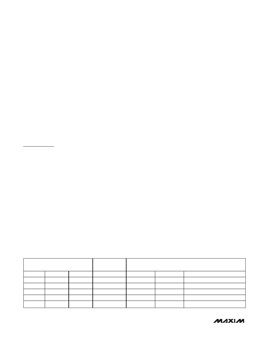
Shutdown Modes
The MAX1102/MAX1103/MAX1104 feature four soft-
ware-selectable shutdown modes, helping to conserve
power by disabling any unused portion of the device.
Bits 0 through 2 of the control word select the device
shutdown mode (Table 1). Table 2 details the four
power modes with the corresponding supply current
and operating sections.
The ADC and DAC are individually controlled and can
be shutdown independently of each other. Bit 0 (E0)
controls the DAC, a logic “1” enables the DAC, a logic
“0” disables the DAC. Bit 1 (E1) controls the ADC, a
logic “1” enables the ADC, a logic “0” disables the
ADC. Either the ADC or DAC or both can be shutdown,
conserving power when one or both converters are not
in use. A fast wake-up time (3s ADC, 10s DAC)
allows the converters to be cycled in and out of shut-
down even during short duration idle times.
Data can be written to the DAC while it is in shutdown.
A control word with A1 = 1 and E0 = 0 disables the
DAC while allowing data to be written to the DAC. The
eight bits following this control word are shifted into the
DAC register. Conversion takes place once the DAC is
enabled.
8-Bit CODECs
14
______________________________________________________________________________________
BIT
SUPPLY
CURRENT
OPERATING SECTIONS
E2
E1
E0
REF
ADC
DAC
00
0
1
A
Off
10
0
18
A
On
Off
1
0
250
A
On
Off
1
0
1
400
A
On
Off
On
1
520
AOn
On
Table 2. Operation Modes
发布紧急采购,3分钟左右您将得到回复。
相关PDF资料
MAX11100EUB+
IC ADC 16BIT SRL 200KSPS 10UMAX
MAX11101EUB+
IC ADC 14BIT SRL 200KSPS 10UMAX
MAX11102AUB+
IC ADC 12BIT SPI/SRL 10UMAX-EP
MAX1111CPE+
IC ADC 8BIT LP 16-DIP
MAX1113CPE+
IC ADC 8BIT LP 16-DIP
MAX1116EKA+T
IC ADC 8BIT SERIAL SOT23-8
MAX11201BEUB+T
IC ADC 24BIT SRL 13.75SPS 10UMAX
MAX11202BEUB+T
IC ADC 24BIT SRL 13.75SPS 10UMAX
相关代理商/技术参数
MAX1104EUA+T
功能描述:ADC / DAC多通道 8-Bit CODEC RoHS:否 制造商:Texas Instruments 转换速率: 分辨率:8 bit 接口类型:SPI 电压参考: 电源电压-最大:3.6 V 电源电压-最小:2 V 最大工作温度:+ 85 C 安装风格:SMD/SMT 封装 / 箱体:VQFN-40
MAX1104EUA+TW
功能描述:ADC / DAC多通道 8-Bit CODEC +2.7V to +5.5V Single Supply RoHS:否 制造商:Texas Instruments 转换速率: 分辨率:8 bit 接口类型:SPI 电压参考: 电源电压-最大:3.6 V 电源电压-最小:2 V 最大工作温度:+ 85 C 安装风格:SMD/SMT 封装 / 箱体:VQFN-40
MAX1104EUA+W
功能描述:ADC / DAC多通道 8-Bit CODEC +2.7V to +5.5V Single Supply RoHS:否 制造商:Texas Instruments 转换速率: 分辨率:8 bit 接口类型:SPI 电压参考: 电源电压-最大:3.6 V 电源电压-最小:2 V 最大工作温度:+ 85 C 安装风格:SMD/SMT 封装 / 箱体:VQFN-40
MAX11054
制造商:MAXIM 制造商全称:Maxim Integrated Products 功能描述:4-/6-/8-Channel, 16-/14-Bit, Simultaneous-Sampling ADCs
MAX11054ECB+
功能描述:模数转换器 - ADC 14Bit 4Ch Simult Sampling RoHS:否 制造商:Texas Instruments 通道数量:2 结构:Sigma-Delta 转换速率:125 SPs to 8 KSPs 分辨率:24 bit 输入类型:Differential 信噪比:107 dB 接口类型:SPI 工作电源电压:1.7 V to 3.6 V, 2.7 V to 5.25 V 最大工作温度:+ 85 C 安装风格:SMD/SMT 封装 / 箱体:VQFN-32
MAX11054ECB+T
功能描述:模数转换器 - ADC 14Bit 4Ch Simult Sampling RoHS:否 制造商:Texas Instruments 通道数量:2 结构:Sigma-Delta 转换速率:125 SPs to 8 KSPs 分辨率:24 bit 输入类型:Differential 信噪比:107 dB 接口类型:SPI 工作电源电压:1.7 V to 3.6 V, 2.7 V to 5.25 V 最大工作温度:+ 85 C 安装风格:SMD/SMT 封装 / 箱体:VQFN-32
MAX11055
制造商:MAXIM 制造商全称:Maxim Integrated Products 功能描述:4-/6-/8-Channel, 16-/14-Bit, Simultaneous-Sampling ADCs
MAX11055ECB+
功能描述:模数转换器 - ADC 14Bit 6Ch Simult Sampling RoHS:否 制造商:Texas Instruments 通道数量:2 结构:Sigma-Delta 转换速率:125 SPs to 8 KSPs 分辨率:24 bit 输入类型:Differential 信噪比:107 dB 接口类型:SPI 工作电源电压:1.7 V to 3.6 V, 2.7 V to 5.25 V 最大工作温度:+ 85 C 安装风格:SMD/SMT 封装 / 箱体:VQFN-32